| |
Residual Stress
Conferences |
  |
Full results in:  The Contour Method, Michael B. Prime and Adrian T. DeWald, 2013, chapter 5 in Practical Residual Stress Measurement Methods, Gary S. Schajer, Editor, pp. 109-138. The Contour Method, Michael B. Prime and Adrian T. DeWald, 2013, chapter 5 in Practical Residual Stress Measurement Methods, Gary S. Schajer, Editor, pp. 109-138.
New rail only published previously in J. Kelleher, M.B. Prime, D. Buttle, P.M. Mummery, P.J. Webster, J. Shackleton,
P.J. Withers, "The Measurement of Residual
Stress in Railway Rails by Diffraction and Other Methods," Journal of Neutron Research, 11(4), 187-193, 2003. (LA-UR-03-7128)
Results:
The contour method results are unprecedented in revealing detailed stress maps in the rails. The longitudinal stresses have changed over the years of service. Wear has produced a compressive stress region at the surface. Plasticity has shifted and increased the sub-surface tensile stress.
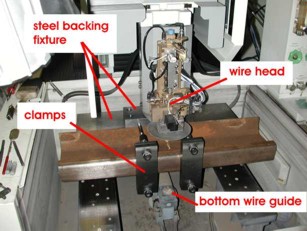
Rail material and EDM Cut:
- Two British rails
- a new roller straightened rail
- a rail that had undergone 23 years of service
- BS 11 normal grade pearlitic steel with the standard 113A profile
- Wire EDM Cut
- Mitsubishi FX-10 wire EDM machine
- 0.25 mm diameter brass wire.
- Epak 1312: skim cut 1 settings for 75 mm thick hardened steel.
|
|
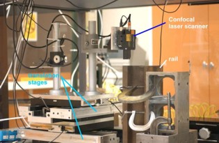
Measure contour:
- Keyence LT-8105 confocal ranging probe
- scanned in the horizontal direction at a sampling rate of 16 points/mm
- rows were spaced vertically to give 4 rows per mm
|
 |
Surface contour:
- Shown on worn rail
- The peak-to-valley range of the contours was about 75 µm
|
 |
3D FEM:
|
 |
3D FEM deformed shape:
- Displacement boundary conditions have been applied to elastically deform the model into the opposite of the shape measured on the cut surface.
|
 |
|
|