| |
Residual Stress
Conferences |
  |
 (preprint) Prime, M. B., Gnäupel-Herold, T., Baumann, J. A., Lederich, R. J., Bowden, D. M., Sebring, R.J., “Residual Stress Measurements in a Thick, Dissimilar Aluminum Alloy Friction Stir Weld,” Acta Materialia, 54(15), 4013-4021, 2006. (LA-UR-06-0512) *** DOI link if you have access to this journal and want the final article instead of a preprint. (preprint) Prime, M. B., Gnäupel-Herold, T., Baumann, J. A., Lederich, R. J., Bowden, D. M., Sebring, R.J., “Residual Stress Measurements in a Thick, Dissimilar Aluminum Alloy Friction Stir Weld,” Acta Materialia, 54(15), 4013-4021, 2006. (LA-UR-06-0512) *** DOI link if you have access to this journal and want the final article instead of a preprint.
paper on the effect of removing the test specimen from a larger plate. "Contour-Method
Determination of Parent-Part Residual Stresses Using a Partially Relaxed
FSW Test Specimen," (LA-UR-04-2131)
For more on residual stress in friction stir welds, see also the papers
by Dalle Donna here.
Results (see below for details):
- This is map of the longitudinal
residual stress over the cross section of a friction stir weld between
2024 aluminum and 7050 aluminum. Two tensile peaks on either side of
the weld are commonly observed for friction stir welds.
- Although fairly low, these
stresses are very important. For example, such residual stresses in
test coupons affect measurements of fatigue crack growth rates
- Contour results compare
very well with neutron diffraction measurements on same part:
- These are line scans at
3 different positions in the above stress map
- Measurements done by Thomas
Gnaupel-Herold at NIST
- Considering low stress magnitudes,
agreement is great
- Agreement is better in weld
and poorer in base material, probably because of microstructural changes
effecting neutron results
Highlights
of this measurement and specimen: ( back
to top)
Specimen:
- Friction
stir weld between 25.4 mm thick plates of aluminum alloys 7050-T7451
and 2024-T351
- A one-pass
single-sided joint was made with the 2024 on the advancing side
- After welding
the panel was aged at 121°C for 24 hours to stabilize the
weld nugget
- Because
of other testing requirements, a small test specimen was removed
for residual stress measurement (see below for effect
of small test specimen)
|
|
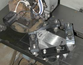
EDM
cutting:
- Picture
shows test piece being cut by wire EDM.
- Cuts were
made using 100 µm brass wire and "skim cut" settings
|
|
Metallography
:
- This is
a micrograph of the weld cross section
- As in the
results at the top of the page, the left side is the 7050, the
right side is the 2024, which is the advancing side of the weld
|
|
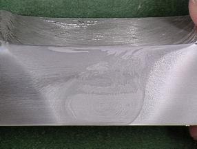
Measure
contour :
- After EDM
cut but before metallography, measure surface contours
- Surfaces
scanned using confocal laser ranging probe
- Peak-to-valley
is about 20 µm
- The low
spots correspond to tensile stress regions
|
|
FEM
stress calculation:
- To calculate
stress, elastically forced FEM model into opposite of measured
contour (shown just above this)
- Displacements
exaggerated to show shape
- Performed
using ABAQUS
|
|
Change
in stresses from removing small test specimen: The residual stresses
were measured in a 54 mm long test specimen that had been removed from
a 457 mm long plate. Because of the short length of the test specimen,
the stresses relaxed somewhat when the specimen was removed. In the paper
(pdf) listed at the top of the page, a method
for calculating how much the stresses relaxed is described. The results
of that estimation are below, showing that the peak tensile stresses were
relaxed by about 25%. (back to top)
Stresses
measured in test specimen (same as results on top of page, just color
scale changed)
Estimated
stress in parent plate prior to stress relaxation caused by removing specimen
|
|